
Latest about EDIS
EDIS generates schematics automatically from the information provided in a EICR
EDIS has many useful features -one of the most exciting is the automatic schematic generation. Using 4 data fields EDIS generates a electrical schematic on a grid- with no CAD or other drawing tools required.
Automated Schematic Creation in EDIS
This document provides a description of how EDIS generates electrical schematics automatically.
You can view the existing schematic : Select EDIS Schematics from the main menu , then Schematic (Beta).
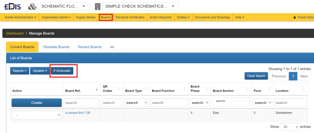
To create the schematic follow the instructions below:
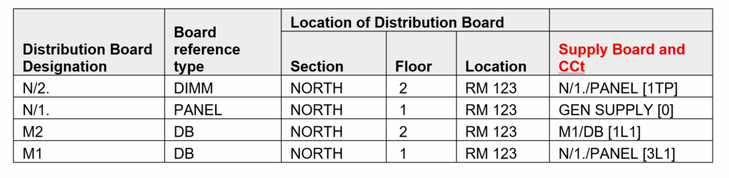
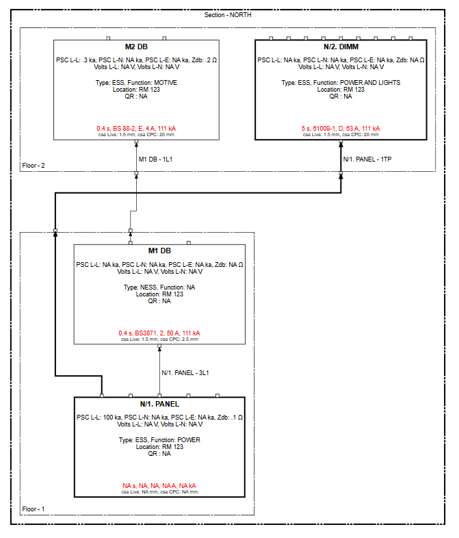
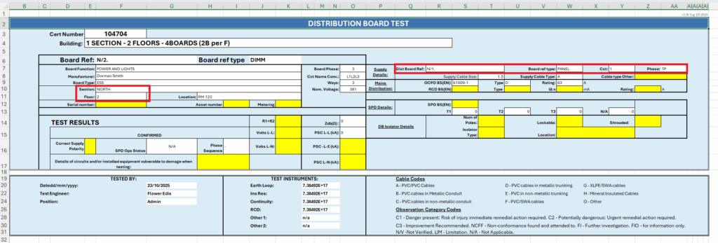
For example assume the following boards setup results in the schematic below, the table on the left shows the details for some example boards:,
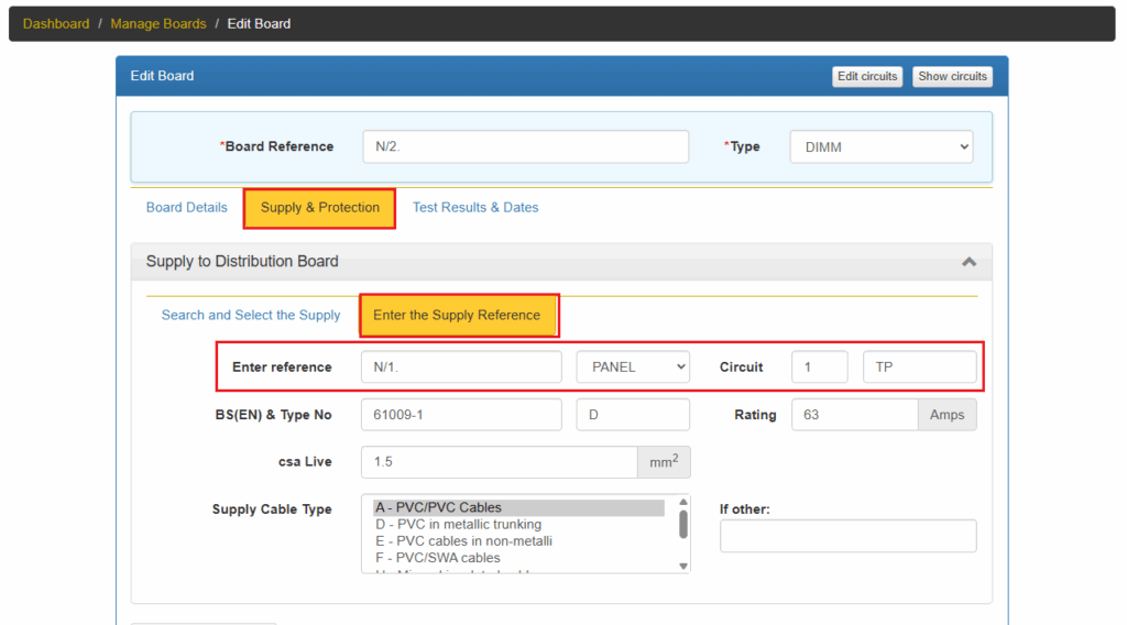
M2 DB is located in Section: NORTH, Floor: 2, and is supplied from M1/DB [1L1]
To create a schematic showing how distribution boards are connected, two key pieces of information for each board is required: its physical location and its power source.
The system or can technician can use this information to place the board on the diagram and draw the line connecting it to its supply.
## 🗺️ Defining the Board’s Location
First, you need to tell the system where the distribution board is physically located in the building. This is done by specifying two details:
Think of this as coordinates on a grid. The Floor acts as the vertical (Y-axis) position, and the Section acts as the horizontal (X-axis) position. By providing these two details, you ensure the board is placed in the correct relative position on the schematic, making the diagram logical and easy to read. If you don’t provide a location, the board might be drawn, but it will be isolated and not part of the building’s logical layout.
The details are described in the section below: Defining the sort order or sequence of the floors and sections.
## ⚡ Defining the Power Source
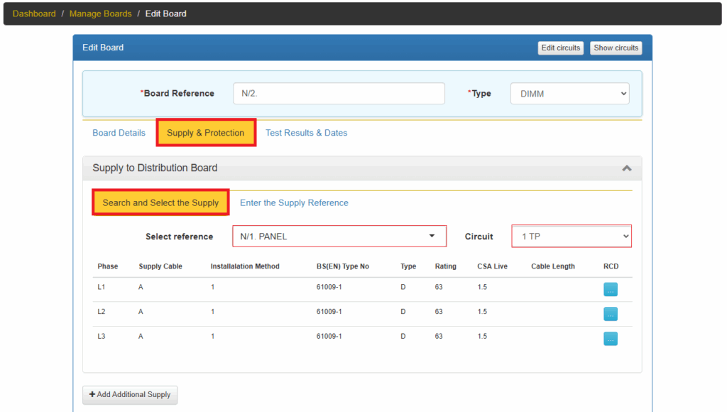
Next, you must identify exactly how the new board gets its power. This is the most crucial step for drawing the connections. You need to provide the source circuit details, which means specifying:
For example, the power source might be identified as ‘DB-GF-MAIN, circuit 1L1’.
This information tells the system to draw a line from circuit 1L1 on the board named DB-GF-MAIN directly to the new board you are adding. Without this information, the system can’t draw the connecting line, and your new board will appear isolated on the schematic without a power source.
Finding this information can be tricky and may require physically tracing the supply cable back to its origin board to identify the correct circuit breaker.
Of course. Here is a more concise and professionally worded set of rules for electrical distribution.
## ⚡️ Rules of Electrical Distribution: Phase Matching
The fundamental principle is that the phase configuration of the supply circuit must match the requirements of the downstream distribution board.
### Three-Phase Source Boards
A three-phase distribution board is versatile and can provide power for both three-phase and single-phase loads.
### Single-Phase ($1\phi$) Source Boards
A single-phase distribution board has a critical limitation.
OPTION 1 EDIT THE BOARDS IN THE BOARD LIST
OPTION 2 EDIT THE BOARDS IN THE CERTIFICATE BOARD LIST
This is the same as option 1, in this case the boards are edited in Step 4 of the certificate wizard.
OPTION 3 EDIT THE BOARDS IN EXCEL WORKSHEET
Using the Excel option to enter the supply details, requires a Condition Report certificate.
5. Upload the excel work sheet to EDIS
6. After uploading the excel worksheet, AND completing the certificate, the distribution board schedule will be updated along with the EDIS Schematic.
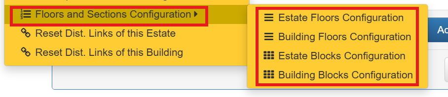
DEFINING THE SORT ORDER OR SEQUENCE OF THE FLOORS AND SECTIONS
When viewing the Schematic you may want to change the sort order of the floors or sections, for example, the floor sort order can be set to: LG, B, B1, 1,M,2,3 – this floor order can be configured using the instructions below, so that the schematic displays the layout correctly.
Using the Administration Menu option the sort order or sequence order of the floors and sections can be define.
| Cookie | Duration | Description |
|---|---|---|
| cookielawinfo-checkbox-analytics | 11 months | This cookie is set by GDPR Cookie Consent plugin. The cookie is used to store the user consent for the cookies in the category "Analytics". |
| cookielawinfo-checkbox-functional | 11 months | The cookie is set by GDPR cookie consent to record the user consent for the cookies in the category "Functional". |
| cookielawinfo-checkbox-necessary | 11 months | This cookie is set by GDPR Cookie Consent plugin. The cookies is used to store the user consent for the cookies in the category "Necessary". |
| cookielawinfo-checkbox-others | 11 months | This cookie is set by GDPR Cookie Consent plugin. The cookie is used to store the user consent for the cookies in the category "Other. |
| cookielawinfo-checkbox-performance | 11 months | This cookie is set by GDPR Cookie Consent plugin. The cookie is used to store the user consent for the cookies in the category "Performance". |
| viewed_cookie_policy | 11 months | The cookie is set by the GDPR Cookie Consent plugin and is used to store whether or not user has consented to the use of cookies. It does not store any personal data. |